
|
|
A graded index fiber is a type of optical fiber cable where the refractive index of the core decreases conitnuously as we move away from the center of the fiber cable. These types of fiber cables are predominantly used for multi mode communication because they offer low intermodal dispersion as compared to multi mode step index fiber. Intermodal dispersion is caused when multiple modes transmitted at the same time from one end of the fiber reaches the other end at different time due to different path taken by each modes. However in graded index fiber, all the modes reaches the destination at the same time if they are sent simultaneously. In this article we will see graded index fiber, various other type of optical fibers available, advantages of using them as compared to step index for multimode communication. Table of Content What is Graded Index Fiber?A graded index fiber is a type of optical fiber where the refractive index of the core gradually changes from the center of the fiber to the edges. This gradual change in refractive index is typically parabolic in nature, and it helps to reduce modal dispersion by causing light rays and follow curved paths through the core. TypesGiven below are the types of Graded Index Fiber Types of fibers Optical fibers can be classified based on their refractive index profiles and the number of modes which can be propogated through them. Based on the refractive index profiles, the optical fiber can be classified as either step index fiber or graded index fiber and based on the modes, the optical fiber can be either single mode or multi mode. Hence there are four major types optical fiber if we take the combination of refractive index profile and number of modes. They are as follows: Single Mode Step Index FiberThese fibers are constructed using core which has a constant refractive index of η1 throughout the radius of the core. The cladding region is having a constant refractive index of η2. Since it is a single mode fiber, it only supports one light signal to pass through the fiber at a given instant of time. Such fibers have small core diameter in the range of 8 ?m to 10.5 ?m and they are used in long distance communication. Multi Mode Step Index FiberThese fibers are constructed using core which has a constant refractive index of η1 throughout the radius of the core. The cladding region is having a constant refractive index of η2. Since it is a multi mode fiber, it supports multiple light signal to pass through the fiber at a given instant of time. These fibers have high capacity, data rate and reliabilty since multiple light signals can be transmitted through a single fiber simultaneously. However these light pulses are spread in time domain till it reaches the end of the fiber. This is called as intermodal dispersion and occurs due to different light signals reaching the detector at different time intervals due to different path taken for propogation. Such fibers have large core diameter in the range of 50 ?m to 200 ?m and they are used in short distance communication, for example backbone networks for building communication, LAN, etc. Single Mode Graded Index FiberThese fibers are fabricated in such a way that the refractive index of the core decreases as we move away from it’s center which has the peak refractive index η1. The cladding region is similar to step index fiber and has constant refractive index of η2. However these fibers are costly as compared to step index fiber since the fabrication process is quite complex. Moreover the graded index profile provides benefit if we propogate multiple modes through the fiber. Hence single mode step index fibers are preferred if we need to send only one mode instead of single mode graded index fiber. Multi Mode Graded Index FiberThese fibers are fabricated in such a way that the refractive index of the core decreases as we move away from it’s center which has the peak refractive index η1. The cladding region is similar to step index fiber and has constant refractive index of η2. Since they are multi mode fibers they support multiple light signals to propogate through the fiber simultaneously. These fibers are usually preferred for multi mode transmission over multi mode step index fibers since they ave less intermodal dispersion. The core diameter of such fibers are in the range of 50 ?m to 62.5 ?m and has similar applications to multi mode step index fibers. Structure of Graded Index FiberIn a graded index fiber, the refractive index of core region gradually decreases when we move away from the center of the core. The refractive index of cladding region is constant and is less than the outermost refractive index of core. This is unlike step index fiber where the refractive index of core is greater than the refractive index of cladding and both are constant. Graded index fiber provides smooth trasition between core-cladding interface and reduces the effect of intermodal dispersion. The refractive index profile determines how slowly or rapidly the refractive index of core changes when we move away from it’s center. The formula for refractive index profile is:
where, ?1 = refractive index of core, Δ = refractive index constrast [Tex](\frac{\eta_{1}-\eta_{2}}{\eta_{1}})[/Tex], a is the core radius of optical fiber, ? is the refractive index profile and r is the variable. If the value of ? is equal to ∞, then the refractive index profile of core is similar to that of step index fiber.  Refractive index profile for different values of alpha 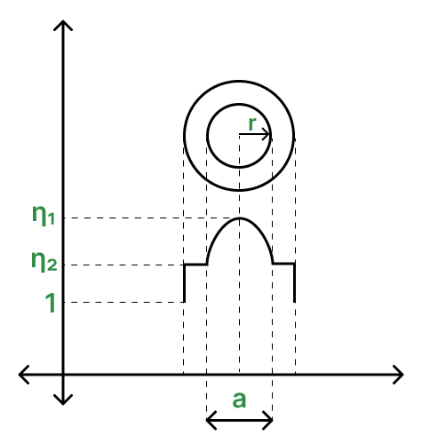 Refractive index profile of graded index fiber Working PrincipleGiven below is the diagram for the working principle 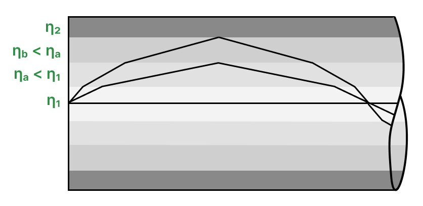 Light propogation through graded index fiber We can understand the working of graded index fiber by observing the above diagram. For understanding purpose let us consider that the refractive index in the core region is varying discretely rather than continuously. Hence they form concentric cylinders having different refractive indices. Consider four regions which are center of the core having refractive index η1 equal to 2, region A having refractive index ηa equal to 1.75, region B having refractive index ηb equal to 1.5 and cladding region having refractive index η2 equal to 1.25. Hence critical angle can be derived as:
Let us consider a light ray having angle of incidence equal to 30° when it goes from center of the core to region A. Since this angle is below the critical angle, total internal reflection does not take place. Instead the light ray is refracted at an angle defined by snell’s law. According to Snell’s law:
Substitute values of η1, ηa, ?i in equation (1) we get,
When light ray travels from region A to region B, the angle of refracted ray from the previous region becomes the angle of incidence for the current region due to mathematical theorem of vertically opposite angle. Since 34.84° is also less than 38.68°, the light ray is refracted again with an angle which can be found by substituting the values of ηa, ηb, ?i in equation (1),
Since 41.79° is greater than 38.68°, the light ray is reflected when it reaches the cladding region and thus total internal reflection takes place. The reverse process occurs where the angle of incidence of the light ray reduces when it passes from region B to center of the core. Suppose if the initial angle of incidence of light ray passing from center of the core to region A was 35°, then the angle of refraction would have been,
Since the angle of refracted ray is higher than the critical angle, the light ray would get reflected early without even going through region B. Since modes are characterized by different critical angles as compared to one another i.e. the light rays may intersect but they do not overlap at the point of incidence. Hence light rays having multiple angle of incidence reaches the destination at the same time in case of graded index fiber thereby reducing intermodal dispersion. In case of actual graded inbdex fiber, where refractive index in the core region continously decreases as we move away from it’s center, the refraction of light takes place continously forming sinusoidal looking propogation of light as shown in the below image.  Multiple modes travelling through graded index fiber The number of modes which are supported by graded index fiber is calculated using V number. The formual for V number is:
Where, NA is the numerical aperture of the optical fiber, a is the core-radius of the optical fiber and ? is the wavelength of the propogated light ray. A fiber is considered to be multimode if the V number is greater than 2.405 and to find the exact number of modes which can be transmitted simultaneously we should take account of refractive index profile of core. Hence total number of modes inside a graded index fiber:
Difference between Step Index and Graded Index Fiber
Advantages of Graded Index FiberGiven below are the advantages of Graded Index Fiber are
Disadvantages of Graded Index FiberGiven below are the Disadvantages of Graded Index Fiber are
Applications of Graded Index FiberApplications of the Graded Index Fiber are
ConclusionThus we saw what is graded index fiber, various types of optical fibers and detailed working of graded index fiber and how it reduces intermodal dispersion which is quite common in case of other multi mode fibers. We also compared step index fiber with graded index fiber and discussed the advantages, disadvantages of graded index fiber along with some practical applications. Frequently Asked Questions on Graded Index Fiber – FAQsWhat is critical angle?
What is Acceptance angle?
What will happen if refractive index of core is less than refractive index of cladding?
|
Reffered: https://www.geeksforgeeks.org
| Electronics Engineering |
Type: | Geek |
Category: | Coding |
Sub Category: | Tutorial |
Uploaded by: | Admin |
Views: | 17 |