|
The 8051 microcontroller always operates on a single bit in a particular memory or register. The location of the bits is specific and it is specified as an offset value in the operand’s low-order end. In this article, we will discuss the logical groups or the logical instructions of the 8051 microcontroller in detail.
Logical Group in 8051
The Logical Group in the 8051 microcontrollers has been divided into 25 different instructions. There is a Carry Flag (CY) which directly affects the instructions of the RRC and RLC in this particular microcontroller. Here are the all instruction groups of the 8051 microprocessor as mentioned below.
| Instruction |
Operation |
Description |
Example |
| ANL |
AND |
Logical AND between operands. |
ANL A, #0x0F |
| ANL |
AND |
Logical AND between accumulator and direct address. |
ANL 20H, A |
| ANL |
AND |
Logical AND between direct address and source operand. |
ANL 20H, #0x0F |
| ORL |
OR |
Logical OR between operands. |
ORL A, #0xF0 |
| ORL |
OR |
Logical OR between accumulator and direct address. |
ORL 20H, A |
| ORL |
OR |
Logical OR between direct address and source operand. |
ORL 20H, #0xF0 |
| XRL |
XOR |
Logical XOR between operands. |
XRL A, #0xFF |
| XRL |
XOR |
Logical XOR between accumulator and direct address. |
XRL 20H, A |
| XRL |
XOR |
Logical XOR between direct address and source operand. |
XRL 20H, #0xFF |
| CPL |
Complement |
Complements all bits in the accumulator. |
CPL A |
| CPL |
Complement |
Complements the specified bit. |
CPL P1.0 |
| CLR |
Clear |
Clears all bits in the accumulator. |
CLR A |
| CLR |
Clear |
Clears the specified bit. |
CLR P1.0 |
| SETB |
Set Bit |
Sets the specified bit. |
SETB P1.0 |
| MOV |
Move |
Moves the carry flag to the specified bit. |
MOV P1.0, C |
| MOV |
Move |
Moves the specified bit to the carry flag. |
MOV C, P1.0 |
Given below is the block diagram of 8051 microcontroller :
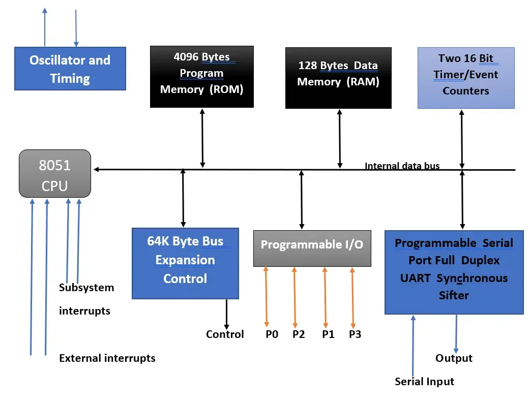 Block Diagram of 8051 Microcontroller Advantages
Here are the advantages of the Logical Group in 8051 as mentioned below.
- Efficient Bitwise Operation : Perform bit-level manipulations quickly and effectively.
- Control and Decision Making : Implement control structures and decision-making processes using bitwise logic.
- Compact and Simple Code : Write concise code that optimizes program memory usage.
- Flexible Data Manipulation : Manipulate data using various operands, providing versatility.
- Bit Manipulation : Directly manipulate individual bits, useful for hardware control.
- Hardware Control : Set and clear specific bits in control registers for hardware manipulation.
- Improved Program Flow : Simplify program flow with intuitive bit-level decision-making.
- Optimized Performance : Execute logical operations quickly, enhancing time-critical application performance.
- Versatility in Applications : Apply logical operations across a wide range of applications, from signal processing to control.
Disadvantages
Here are the disadvantages of the Logical Group in 8051 as mentioned below.
- Limited Operand Size : Restricted to 8-bit operations, problematic for larger data sizes.
- Increased Code Complexity : More complex code is required for handling data larger than 8 bits.
- No Direct Support for High : Level Operations – Requires building complex operations from basic instructions.
- Limited Instruction Set : Fewer specialized instructions compared to modern microcontrollers.
- Resource Constraints : Must manage limited resources carefully to avoid excessive use of registers and memory.
- Performance Bottlenecks : Complex operations involving multiple logical instructions can slow down performance.
- Debugging Complexity : Tracing bit-level manipulations can be challenging during debugging.
- Lack of Built-in Support for Complex Operations : Complex logical operations require multiple instructions, increasing code complexity and size.
Applications
Here are some applications as mentioned below.
- Digital Signal Processing : Filtering and bit manipulation in DSP tasks.
- Embedded Systems : Control systems, sensor data processing, and hardware control.
- Communication Protocols : Error detection/correction, data encoding/decoding.
- User Interface Management : Keypad/button handling, LED control.
- Timing and Counting Applications : Timer/counter configuration, event counting.
- Memory and Data Management : Bitwise data storage, data compression.
- Security and Encryption : Simple encryption algorithms, password protection.
- Real-Time Systems : Interrupt handling, state machines.
Conclusion
The 8051 microcontroller always operates on a single bit in a particular memory or register. The location of the bits is specific and it is specified as an offset value in the operand’s low-order end. There is a Carry Flag (CY) which directly affects the instructions of the RRC and RLC in this particular microcontroller. In this article, we have learned about the Logical Group in 8051 in detail.
People Also Read
Logical Group in 8051 -FAQs
What is a logical group of instructions?
Logical Group performs logical (Boolean) operations on data in registers and memory and on condition flags. The logical AND, OR, and Exclusive OR instructions enable you to set specific bits in the accumulator ON or OFF.
What are the instruction groups of 8051?
The 8051 instruction set has different type of instructions based on their operation. They are Data transfer, Arithmetic, Logical, Boolean, and Branching instructions.
What is logical instructions in microcontroller?
Logical instructions in the 8085 microprocessor are a set of instructions that perform logical operations on data in registers and memory. Logical operations are operations that manipulate the bits of data without affecting their numerical value. These operations include AND, OR, XOR, and NOT.
What is the logical group of 8051?
In 8051 Microcontroller there is 25 different instructions under the Logical Group. In total there are 49 opcodes.
What is the RL instruction in 8051?
The RL instruction rotates the eight bits in the accumulator left one bit position. Bit 7 of the accumulator is rotated into bit 0, bit 0 into bit 1, bit 1 into bit 2, and so on. No flags are affected by this instruction.
|