
|
|
While dealing with electrical circuits, sometimes it is required to amplify the signal to a certain amount. This amplification can be performed by a device named an operational Amplifier which has a certain gain associated with it. In this article, we will study the op-amp and try to understand the working principle behind an op-amp. We will also study the applications of op-amp and use certain examples to understand the applications better. Later we will study the advantages and disadvantages of op-amp and discuss the possible future trends in an op-amp. The article will conclude with some frequently asked questions that readers can refer to. Table of Content What is Op-Amp?The term op-amp stands for operational amplifier. It can be described as a multistage amplifier that has a gain value associated with it. An operational amplifier is used for different purposes like amplification, subtraction, differentiation, addition, integration, etc. The internal circuitry of an op-amp is complicated since it includes transistors, FETs, and resistors to form a multistage amplifier. Next, we will go through the Working of the Op Amp. Working Principle of Op AmpGiven Below is the circuit diagram of the Operational Amplifier
A simple amplifier consists of two input terminals and one output terminals as shown. Let us see how the op-amp works when an input is fed to the terminal of the op-amp.
Applications of Op AmpLet us study the applications of the op-amp:
Op Amp As Signal AmplifierOp-amps are used for Signal amplification. Every op-amp has a certain gain associated with it and the output signal generated is the input signal multiplied by the gain of the multiplier. This is generally used in applications that involve weak signals which need to be amplified for different purposes. The input is fed to the two input terminals of the op-amp and is amplified. Op Amp As FiltersOp-amps are used in filters. They are used to implement filters such as low-pass, high-pass, band-pass, and band-stop filters. The particular characteristics that make op-amps useful in filters are their high gain, high input impedance, and low output impedance characteristics. These filters are then used to block and pass certain frequencies depending on the requirements. L at the circuit used in this conversion with a mathematical formula. .webp) Op-amp in Low Pass Filter
Op Amp As Voltage ComparatorsOp-amps are used in comparators for comparing the input voltages. The input voltages to be compared are fed at the inverting and non-inverting terminal of the op-amp and a digital output is generated. This is useful in appliances like threshold detection, window comparators, and zero-crossing detectors in control systems, oscillators, and sensor interfaces. L at the circuit used in this conversion with a mathematical formula. .webp) Voltage Comparator
Op Amp As OscillatorsOp-amps are used in making oscillators. The oscillator performs oscillations at a periodic interval to generate waveforms like sine waves, square waves, and triangular waves which are periodic. These oscillators are used in devices that need to keep track of periodic waveforms like clock generators, and audio oscillators. L at the circuit used in this conversion with a mathematical formula. .webp) Op-amp oscillator circuit
Op Amp As DifferentiatorOp-amps are used largely in Integrator and Differentiator Circuits. The differentiator circuits as the name suggests generate a voltage proportional to the derivative of the input voltage fed to the op-amp. These circuits are very useful for signal processing and generating all the required signals. Look at the circuit used in this conversion with a mathematical formula.  Differentiator Circuit
Op Amp As IntegratorOp-amps are used largely in Integrator and Differentiator Circuits. The integrator circuits as the name suggests generate a voltage proportional to the integral of the input voltage fed to the op-amp These circuits are very useful for signal processing and are used for different purposes. Look at the circuit used in this conversion with a mathematical formula.  Integrator circuit
Op Amp As Voltage to Current ConverterOp Amps are used as voltage-to-current converters where they can change the input voltage to generate current. This is done by applying a feedback circuit to the op-amp using certain resistances and current sources. Note that one popular op-amp used for voltage-current conversion is IC LM741 which generates enough current. Look at the circuit used in this conversion with a mathematical formula.  Voltage to Current CoVoltage to Current Converternverter
Op Amp As Current to Voltage ConverterOp Amps are used as Current to Voltage Converter where the input current is used to generate the voltage. A feedback circuit made up of resistors and current sources, is used for generating the voltage when input is fed at the inverting terminal of the op-amp. The non-inverting terminal is usually grounded as shown below. Look at the circuit used in this conversion with a mathematical formula.  Current to Voltage Converter
Op Amp As Logarithmic AmplifierOp Amp is used as Logarithmic a Amplifier. As the name suggests, logarithmic amplifiers are devices made using op-amps that perform mathematical tasks like calculating the logarithm and anti-logarithm values along with the amplification of the signal. The output generated in such devices is proportional to the logarithm of the applied input. Look at the circuit used in this conversion with a mathematical formula.  Logarithmic amplifier
Op Amp As Half Wave RectifierOp Amps are used as a Halfwave Rectifier. Rectifiers are devices that convert the AC input fed to them into DC output. The term ‘half-wave’ is used to indicate that this type of rectifier only generates positive half cycles for half the cycle and generates zero output for the remaining half cycles. Another type rectifiers are full-wave rectifiers that can covert AC input to DC output for full cycles. Look at the circuit used in this conversion with a mathematical formula.  Half wave rectifiers
Op Amp As Peak DetectorOp Amps are used as a Peak Detector for measuring a certain peak in the input signal. While dealing with signals, we often feel the need to measure the maximum or the peak value of a signal, and an op-amp can be used to solve this problem. This is usually done by measuring the threshold voltage and changing the diode bias according to block or pass the current. Look at the circuit used in this conversion with a mathematical formula. Look at the circuit used in this conversion with a mathematical formula.  Peak Detector
Op Amp As Non-Inverting AmplifiersTill now, we have seen that operational amplifiers are used as amplifiers and this can be done in mainly two configurations. One of which is a non-inverting amplifier. The important thing about this configuration is that the input voltage signal is applied directly to the non-inverting terminal of the op-amp. Since the signal is fed to the non-inverting terminal, the mathematical calculation shows that it results in a positive gain with an “in-phase” output signal. Look at the circuit used in this conversion with a mathematical formula. 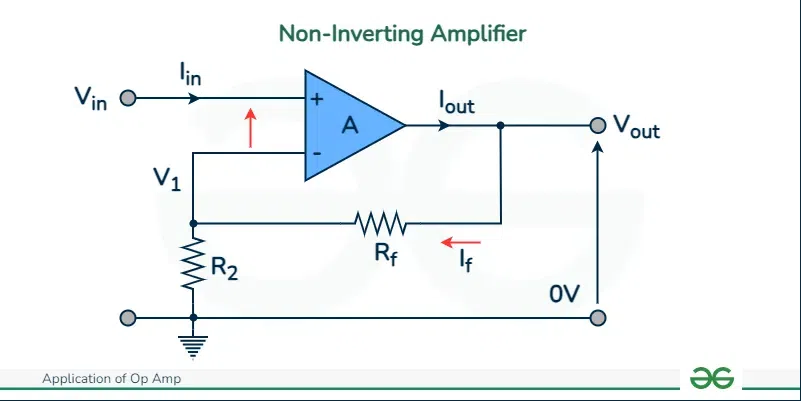 Non-Inverting Amplifier
Op Amp As Inverting AmplifiersAnother configuration of using op-amp as an amplifier is inverting amplifier configuration. The important thing about this configuration is that the input voltage signal is applied directly to the inverting terminal of the op-amp. Since the signal is fed to the inverting terminal, the mathematical calculation shows that it results in a negative gain with an “out-of-phase” output signal. Look at the circuit used in this conversion with a mathematical formula.  Inverting Amplifiers
Op Amp As Phase ShifterThe term phase shifter is used for a device that can change the phase of the signal without changing the original amplitude of the signal. These circuits are usually designed using resistors, capacitors, and operational amplifiers. The phase of the signal is controlled by changing the resistance value of the programmable resistor. Look at the circuit used in this conversion with a mathematical formula. 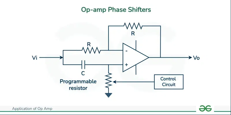 Op-amp Phase Shifters
Op Amp As Scale ChangerAn operational amplifier can also be used as a scale changer for comparatively small signals. It is used as a scale changer in inverting as well as non-inverting amplifiers. Here is a circuit for understanding how is op-amp used as a scale changer. If you carefully observe, you will see that the non-inverting terminal is grounded and the signal is fed to the inverting terminal with a resistance value of R, this results in a negative feedback system.  Op-amp as a Scale Changer Op Amp As Adder or Summing AmplifierThe name “Summing Amplifier” is used since op-amps can be used to add two or more input voltages and generate a single output from it. It is important to note that input voltages are applied to the inverting terminal of the op-amp while the non-inverting terminal is grounded. The below circuit shows op-amp as an adder. Look at the circuit used in this conversion with a mathematical formula that shows that the output voltage is proportional to the sum of input voltages. 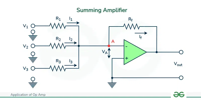 Summing Amplifier
Examples of Op AmpLet us study the examples of the op-amp
Advantages of Op AmpLet us study the advantages of the op-amp
Disadvantages of Op AmpLet us study the disadvantages of the op-amp
Future TrendsWith an advancement in technology, it is evident that there will be developments in operational amplifiers. These developments can be expected regarding the op-amp design, its performance, efficiency, and reliability. With the integration technology, it is expected that the future op-amps can be integrated onto a single chip to obtain a miniaturized version that can use the available space efficiently. Other developments in the op-amp can be seen in terms of reducing the power consumption of the op-amp, this can also result in environmentally sustainable devices that can reduce the electronic waste produced. This is how developments can be expected in op-amp in the coming time. ConclusionWe have seen how op-amps form an integral part of electrical engineering. The ability of op-amps to amplify the input signal is utilized in different appliances like amplifiers, filters, and comparators. It is necessary to understand the working principle of op-amps to design the op-amp depending on the needs of your circuit. Despite the various advantages offered by op-amps, there are certain limitations associated with op-amps which have been discussed in the article. Readers are advised to refer to the frequently asked questions in case of any doubt. Applications of Op Amp – FAQsWhat are the two types of op-amps?
What is the input and output resistance of an op-amp?
What is an ideal operational amplifier?
|
Reffered: https://www.geeksforgeeks.org
| Electric Circuits |
| Related |
|---|
| |
| |
| |
| |
| |
Type: | Geek |
Category: | Coding |
Sub Category: | Tutorial |
Uploaded by: | Admin |
Views: | 14 |