
|
|
In this Article, We will be going through the RL Parallel Circuit, We will start our Article with the Introduction of the RL Parallel Circuit, Then we will go through the Circuit Diagram of the RL Parallel Circuit where we will calculate circuit parameters and See its phasor Diagram, Then we will calculate Power and Impedance of the Parallel Circuit, At last we will conclude our Article withExample, Applications, and Some FAQs. Table of Content What is RL Parallel Circuit?An RL parallel circuit is formed when a resistor and an inductor are connected in parallel and driven by the same voltage source. Unless it is powered by a current source, the parallel RL circuit is generally less interesting than the series circuit. This is mostly because this circuit does not act as a voltage input filter. After all, the output voltage (Vout) and input voltage (Vin) are equal. Many amplifier designs include a parallel circuit on the output that is used to protect the amplifier from high-frequency capacitive loading effects. Certain amplifiers develop instability and oscillation at very high frequencies as a result of capacitance-induced phase shift. An electric circuit having resistance and self-inductance is another way to define an RL circuit. We already know that when an EMF source is applied by a constant variation in the magnetic flux, the induction process takes place. Self-inductance is the result of a device coming into contact with its own Faraday laws of induction, whereas mutual inductance is the result of Faraday’s laws of induction. A component of a circuit or device that demonstrates self-inductance is called an inductor. An RL circuit will use energy, much like an RC or RLC circuit, because a resistor is present in the optimal version of the circuit. Circuit Diagram of RL Parallel CircuitIn the RL parallel circuit diagram, the R and L are connected in parallel. The parallel property of the circuit is defined as the division of current in branches. If we consider the heat and energy then the Resistor provides heat loss and the inductor gives the magnetic store energy. The circuit diagram is shown below. RL Parallel Circuit the shown diagram is for the A.C applied source. Where, R is the Resistor L is the Inductor VR = VL = Vsupplied (in parallel Combination) So, [Tex]IR = \frac{Vsupplied}{R} [/Tex] [Tex]I_L = \frac{Vsupplied}{X_L} [/Tex] [Tex]I_L={Vsupplied}{jωL} [/Tex] ( XL = jωL ) Where,ω is the frequency of applied signal So the Final Equation can be Written as [Tex]I_L=-j \frac{Vsupplied}{\omega L} [/Tex] As we know [Tex]\frac{1}{j}=-j[/Tex] Phasor Diagram of RL Parallel circuit
 Phasor diagram we know cos(φ) is power factor Total current (IT) can be written as [Tex] I_T^2=I_L^2+I_R^2[/Tex] So,as we Know the Value of [Tex]I_L[/Tex] ,the [Tex]I_T[/Tex] can be Written as [Tex]I_R=\frac{V_{in}}{R}[/Tex] [Tex]I_L=-j \frac{Vsupplied}{\omega L} [/Tex] Total current [Tex]I_T=\frac{V_{in}}{R-j\frac{V_{in}}{\omega L}}[/Tex] Power in Parallel RL CircuitTrue power (W) is the power dissipated by the resistive branch, while reactive power (VARs) is the power returned to the source by the inductive branch. Together, these two types of power are referred to as VA (apparent power) in the parallel RL circuit. Power Factor =cos(φ)=[Tex]\frac{I_R}{I_T}=\frac{I_R}{\sqrt{I_L^2+I_R^2}}[/Tex] The voltage drop across the resistor multiplied by the current passing through it yields the true power in watts. W = VR x IR The voltage drop across the inductor times the current passing through it equals the reactive power in VARs. VARs = VL x IL The applied voltage multiplied by the total current yields the apparent power in VA.  Power Triangle for a RL Parallel Circuit The current in each branch of a parallel RL circuit acts independently of the currents in the other branches, as is the case in all parallel circuits. Each branch’s current flow is dictated by the voltage across it as well as any resistance or inductive reactance that may be present in the branch to impede current flow. Parallel RL Circuit Impedance RL Circuit Impedance The total resistance to the current flow in a parallel RL circuit is known as the impedance (Z). It consists of the inductive reactance (XL) provided by the inductive branch and the opposition (R) provided by the resistive branch. In the Given Circuit Resistance and Inductor are parallel So,Calculating the impedance Z we have, [Tex]\frac{1}{Z}=\frac{1}{R}+\frac{1}{jX_L}[/Tex] Z=[Tex]\frac{R \times jX_L}{R+jX_L}[/Tex] Now Dividing the numerator and denominator by R-jXL Z=[Tex]\frac{R \times jX_L}{R+jX_L} \times \frac{R-jX_L}{R-jX_L}[/Tex] [Tex]\frac{jR^2X_L-j^2R^2X_L^2}{R_2+X_L^2}[/Tex] We know j2 =-1 Z=[Tex]\frac{RX_L^2}{R^2+X_L^2}+j\frac{R^2X_L}{R^2+X_L^2}[/Tex] Examples on RL paraller circuitFor the parallel RL circuit shown in Figure, determine: 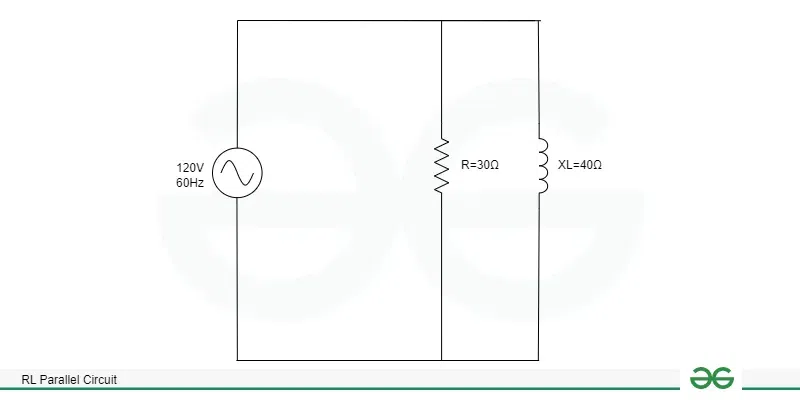 Example
Applications
ConclusionAn RL circuit can also be defined as an electric circuit having self-inductance plus resistance. We also know that the induction process occurs when an emf source is applied through a continuous change in the magnetic flux. While mutual inductance is the outcome of Faraday’s laws of induction, self-inductance is the effect of a device comes into contact with its own Faraday laws of induction. An inductive element is a part of a circuit or apparatus that displays self-inductance. Because a resistor is a part of the ideal circuit, an RL circuit will use energy, just like an RC or RLC circuit, because the ideal version of the circuit contains a resistor.The main parts of a first-order RL circuit include one resistor and one inductor. The low power factor of the circuit is caused by the inductive load, such as a three-phase induction motor. None of the lights, transformers or welding equipment work at low leading power factor values. FAQs on RL parallel circuitWhat is an RL circuit’s power factor?
Which applications are there for RL circuits?
Define RL circuit
What is an RL series circuit’s time constant?
|
Reffered: https://www.geeksforgeeks.org
| Analog And Digital Electronics |
Type: | Geek |
Category: | Coding |
Sub Category: | Tutorial |
Uploaded by: | Admin |
Views: | 15 |