|
|
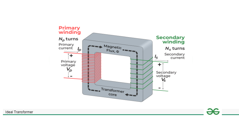
In this article, we will look into a special type of transformer known as the Ideal Transformer which is designed in ideal condition with no loss and 100% efficiency. We will discuss what is a transformer, ideal transformer. We will look into the working principle, properties, and equations of the ideal transformer. We will also look into an ideal transformer with load and with no load. In addition to these, we will also see the phasor diagram. Later, we will discuss the advantages, disadvantages, and applications of, the ideal transformer. Table of Content What is a Transformer?A transformer is a device that transfers electrical energy between two or more circuits. It is used for AC and is used for changing the voltage without changing the frequency. These types of transformers are known as step-up and step-down transformers. It uses the principle of electromagnetic induction for the transfer of energy. Transformers typically consist of two coils of wire these are known as primary and secondary windings. Ideal TransformerAn Ideal Transformer is a type of imaginary transformer used as a theoretical approach to analyze the behavior of real transformers. This transformer does not have any loss of power, so the efficiency is 100%.In an Ideal Transformer, there is no leakage flux which means that the magnetic flux generated by the Primary winding will be linked with the secondary will have no loss. Also, an ideal transformer operates without magnetic saturation, maintaining linear magnetic properties regardless of the applied voltage or current. Ideal Transformer Working PrincipleIdeal Transformer is based on the principle of electromagnetic induction. The primary and secondary windings are wrapped around a common magnetic core. When the current flows through the primary winding, a magnetic field is created. This magnetic field induces a voltage in the secondary winding. Equations of Ideal TransformerIn ideal transformer, as there is no loss and has 100% efficiency. Therefore, input power will be equal to output power. We can write it as, [Tex]E_2I_2\cos\phi=E_1I_1\cos\phi \newline => \frac{E_2}{E_1}=\frac{I_1}{I_2}[/Tex] We can write the conversion ratio as, [Tex]\frac{V_2}{V_1}=\frac{E_2}{E_1}=\frac{N_2}{N_1}=\frac{I_1}{I_2}=K[/Tex] Ideal Transformer With LoadIdeal transformer with load is a type of transformer where a load is connected to secondary winding of the ideal transformer. When current flows through the secondary section a magnetic field is created around it, by the principle of electromagnetic induction the changing magnetic field induces a voltage in the primary part of the transformer. The ratio of number of turns in the primary to the number of turns in the secondary part will determine the ratio of voltage in the primary and secondary part. 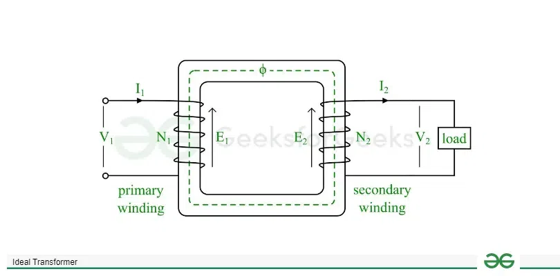 Ideal transformer with load Let’s consider a load of [Tex]Z_L[/Tex] is connected to the secondary part of the transformer. This will induce an EMF E2 along with current I2. So, we can write, [Tex]I_2=\frac{E_2}{Z_L}=\frac{V_2}{Z_L}[/Tex]. ([Tex]E_2=V_2[/Tex] in case of ideal transformer) I2 current flowing in the secondary part creates a magnetomotive force. This force produces a flux which is in the opposite direction of the main flux. This flux will make some changes in the core flux. to counterbalance the flux the primary current should be, [Tex]N_1I_1=N_2I_2 \newline \Rightarrow I_1=\frac{N_2}{N_1}*I_2[/Tex] 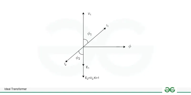 Phasor Diagram The phasor diagram of the ideal transformer with load is given below where, the current I2 will lag behind the EMF E2 because we assumed the load to be inductive. The lagging angle will be [Tex]\phi_2[/Tex] . Also, we will not consider the load current as the transformer is in ideal condition. Ideal Transformer With No LoadIn this type of ideal transformer there is no load connected to the secondary part of the transformer hence, no current flows through this part. As there is no current in the secondary part, no voltage is induced in the primary part. The current that flows through the primary part is the magnetizing current that is required to establish the magnetic field in the core of the transformer. The primary current is due to the applied voltage and the inductance of the primary coil.  Ideal transformer with no load An input voltage [Tex]V_1[/Tex] is given to the primary winding of the transformer because of which a small magnetizing current [Tex]I_m[/Tex] flows through the primary winding. This current produces a flux which induces [Tex]E_1\: \: and \:\: E_2[/Tex] in primary and secondary respectively. 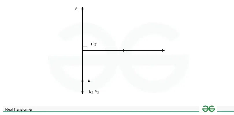 Phasor Diagram As the current in the secondary winding is zero, there is only magnetizing current which lags 900 of the input voltage V1. The induced EMFs E1 and E2 are inversely proportional to the input voltage. Properties of an Ideal Transformer
Advantages of Ideal Transformer
Disadvantages of Ideal Transformer
Applications of Ideal Transformer
ConclusionIn conclusion, Ideal transformer is a theoretical concept that is used to analyze the behavior of the transformer. This transformer has 100% efficiency and zero loss. This is very much useful for understanding the basic principles of the transformer. Although it is useful for understanding and analyzing the practical transformer operation differs from it. In practical applications there is losses, flux leakage and many other factors that are needed to be considered. Ideal Transformer – FAQsWhich law is used in Transformer?
What is rating in transformer?
What is the efficiency of a transformer?
|
Reffered: https://www.geeksforgeeks.org
| Electrical Engineering |
Type: | Geek |
Category: | Coding |
Sub Category: | Tutorial |
Uploaded by: | Admin |
Views: | 14 |