
|
|
Logic gates are those devices that work as the major component of different digital circuits. These digital components perform specific logical functions or Boolean logic operations with one or multiple binary inputs. In this article, we are going to discuss the different applications of logic gates in detail. Table of Content Applications of Logic GatesThere are around five major types of logic gate and each gate has its working procedure and application. Let us discuss this in detail. OR GateThe OR gate has at least two or more two inputs with one output. In general, the output of the OR gate is high as the inputs of the gate are high. It implements the logical disjunction process. OR Gate Logic Diagram and Truth TableHere is the logic diagram and truth table of the OR gate as mentioned below. OR Gate Applications of OR GateThere are different types of applications of OR gates in different sectors as mentioned below.
AND GateThe AND gate is a digital circuit. The circuit consists of two or multiple inputs and just one output. If we give the low input, the output value will be low. It is easy to test and perform troubleshooting operations. AND Gate Logic Diagram and Truth TableHere is the logic diagram and truth table of the AND gate as mentioned below.  AND Gate Applications of AND GateThere are different types of applications of AND gates in different sectors as mentioned below.
NOT GateThe NOT gate is a digital circuit that has only one input and only one output. The NOT gate is also known as the inverter that inverses the input value as output. The symbol of the NOT gate looks like a triangle where a bubble is present over it. NOT Gate Logic Diagram and Truth TableHere is the logic diagram and truth table of the NOT gate as mentioned below.  NOT Gate Applications of NOT GateThere are different types of applications of NOT gates in different sectors as mentioned below.
NOR GateThe NOR gate is an inverter of the OR gate. It means, that if we make fixed the output of the OR gate, it will become a NOR gate. The NOR gate is the customized version of the NOT-OR gate. The NOR gate can perform NOR operations by taking two binary inputs to produce a binary signal. The NOR gate is also known as the universal gate because it individually can create any digital circuit. NOR Gate Logic Diagram and Truth TableHere is the logic diagram and truth table of the NOR gate as mentioned below.  NOR Gate Applications of NOR GateThere are different types of applications of NOR gates in different sectors as mentioned below.
NAND gateThe NAND gate is also a universal gate that can create other gates as per the requirements. The NAND gate is a NOT-AND gate that performs the inverted AND function. The NAND gate can implement any Boolean function independently without taking the help of any other primary gates. NAND Gate Logic Diagram and Truth TableHere is the logic diagram and truth table of the NAND gate as mentioned below. 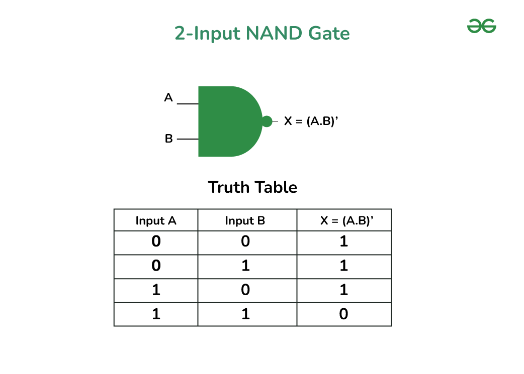 NAND Gate Applications Of The NAND GateHere are the applications of NAND gates as mentioned below.
ConclusionLogic gates are those devices that work as the major component of different digital circuits. The OR gate has at least two or more two inputs with one output. In general, the output of the OR gate is high as the inputs of the gate are high. The OR gates are used to make alarms including fire alarms. If the sensor detects smoke, the OR gate creates a signal to trigger the alarm. The AND gate is a digital circuit. The circuit consists of two or multiple inputs and just one output. AND gates are used to design different decision-making devices where multiple conditions are present. In the interlocking system, the AND gates are used to satisfy the multiple conditions. NOT gates are used to design flip-flops and latches to build memory blocks in computers. The gate is also used to design RAM and registers used in processors. People Also Read:
Frequently Asked Questions on Applications of Logic Gates-FAQ’SWhat is a real life application of AND gate?
What is a real life application of NAND gate?
|
Reffered: https://www.geeksforgeeks.org
| Electronics Engineering |
| Related |
|---|
| |
| |
| |
| |
| |
Type: | Geek |
Category: | Coding |
Sub Category: | Tutorial |
Uploaded by: | Admin |
Views: | 17 |